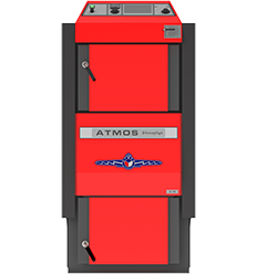
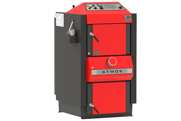
Gasification boiler for wood
- Automatic wood ignition
- Technical details
- High performance boilers
-
DC32S
-
Rated power 35 kW
-
Boiler efficiency 88,9 %
-
Emission class nr. 5 (Ecodesign)
-
Log lenght 530 mm


Advantages of Wood Gasification Boilers ATMOS
- Option to burn large pieces of wood
- Large space for wood – long burning time – up to 12 hours, depending on boiler type
- High efficiency 87 – 92 % – primary and secondary air is preheated to a high temperature
- Ceramic combustion chamber
- Ecological burning – boiler class 5 – EN 303-5:2012, ECODESIGN 2015/1189
- Exhaust fan – dust-free ash removal, smokeless boiler room
- Cooling loop protecting against overheating – without risk of boiler damage
- Automatic shutdown of the boiler after the fuel has burned out – flue gas thermostat
- Comfortable ash removing – large space for ash (when burning wood, clean it 1x / week)
- Boiler without tube heat exchanger – easier cleaning
- Small size and low weight
- Possibility of choosing a door R / L (right/left) for selected types
- Possibility of connection without accumulation tank
- High quality
-

- DC18S
-
- DC32S, DC40SX
-
- DC70S
-
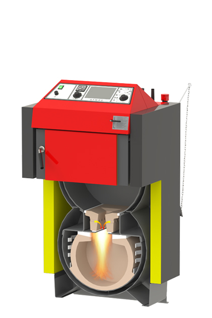
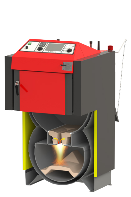
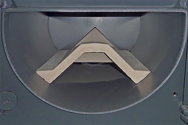
- Combustion chamber with heat-resistant fitting – nozzle
-
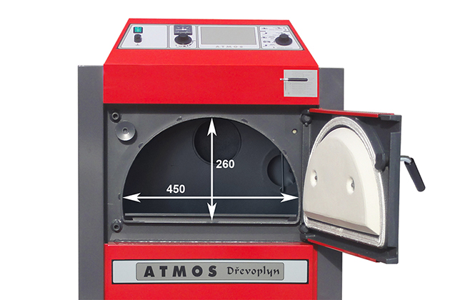
- Filling hole dimensions
-
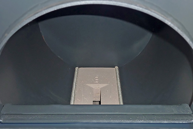
- View of bottom combustion chamber
-
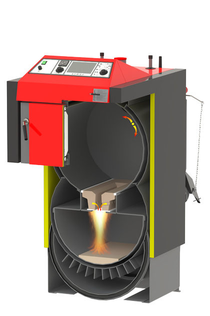
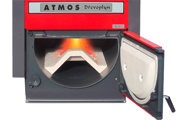
- Flame in the lower combustion chamber
-
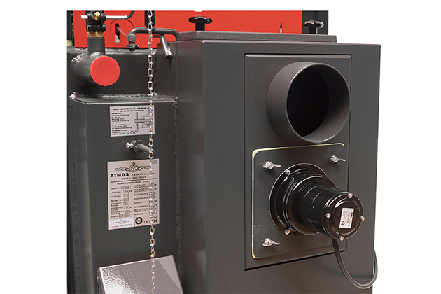
- Exhaust fan and flue gas neck
-
- Upper cleaning lid at the rear of the boiler
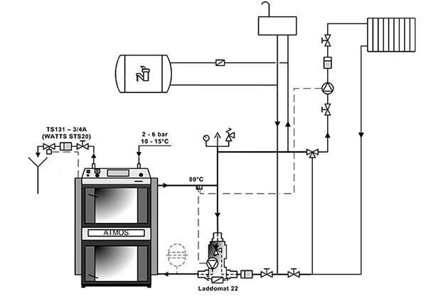
Installation
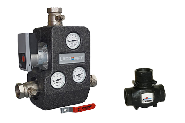
ATMOS boilers must be connected via the LADDOMAT 22 or ESBE thermoregulation valve (three-way valve controlled by actuator in case of using electronic regulation ACD 03/04) to achieve keeping the minimum temperature of water returning to boiler at 65 °C. We keep the outlet temperature of the boiler in the range of 80 – 90 °C and set the temperature of the water to the radiators or floor heating on the mixing three-way valve as needed (e.g. 30 – 80 °C). The default configuration of all boilers includes a cooling circuit to prevent overheating. We recommend installing a boiler with accumulation tanks, which will reduce fuel consumption and increase heating comfort.
-
- Laddomat 22
-
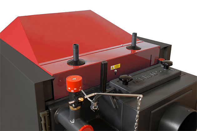
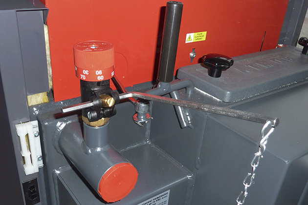
- Cooling loop against overheating and draught regulator FR124
-
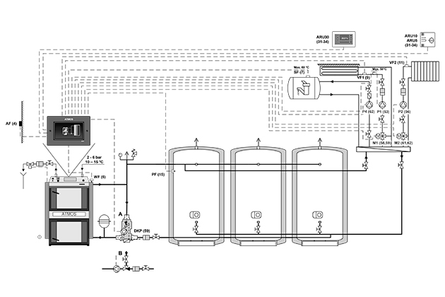
- Boiler wiring diagram with ACD 03 control and storage tanks
-
- Boiler wiring diagram with Laddomat 22 without storage tanks
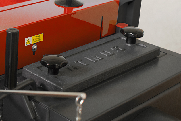
Boilers regulation
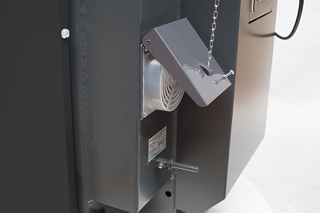
Electromechanical regulation – boiler performance is regulated by an air regulating valve controlled by a draft regulator, FR 124 type, which automatically opens or closes the air valve according to the set water outlet temperature (80 – 90 °C). In addition to performance regulation, the draft regulator helps protect the boiler against overheating. Its advantage is a quick ignition and firing up to the required output when the air valve is fully open. The boilers are equipped with a control thermostat on the instrument panel, which controls the exhaust fan according to the set water outlet temperature (80 – 85 °C) and a flue gas thermostat, which is used to shut down the boiler and turn off the exhaust fan after the fuel has burned out. In the case of connecting a boiler with accumulation tanks, the flue gas thermostat also controls the operation of the pump in the boiler circuit.
The advantage of regulation and design of ATMOS boilers is that the boilers work with a good chimney draft up to 70 % of the nominal power even without a fan.
-
- Regulating air flap
-
- Draught regulator FR 124
-
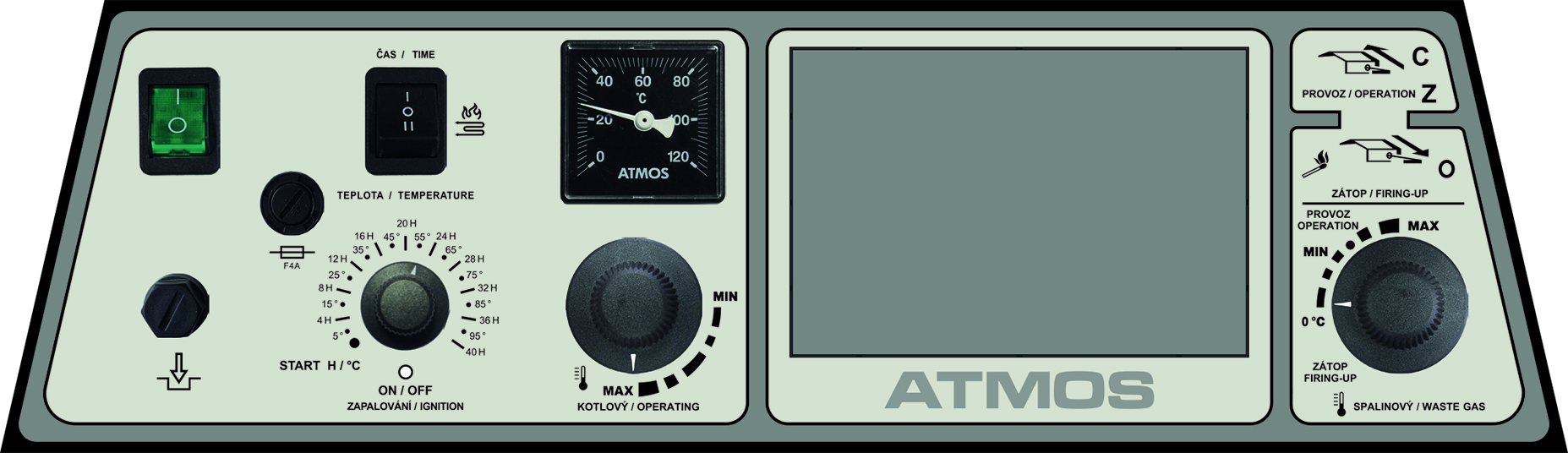
- Boiler control panel with standard regulation
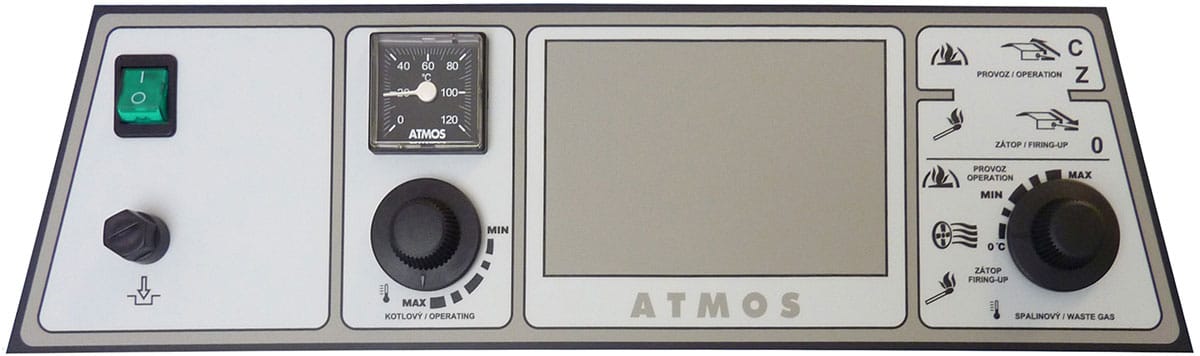
Panel composition:
Main off switch, safety thermostat, thermometer, regulator thermostat and combustion thermostat
Electro-mechanical regulation is an optimum solution for easy management of the operation of the boiler (ventilator). The design of the panel with standard regulation is a basic design for all produced boilers.
Equithermal regulation ACD 03
Each boiler can be equipped with a modern touch electronic control ATMOS ACD 03 for controlling the entire heating system depending on the outdoor temperature, room temperature and time. It´s designed for comfortable control of the hot water system of the heated building. The controller contains functions for direct control of the boiler, boiler circuit, three heating circuits, domestic hot water, solar, etc.
-
- Boiler control panel with equithermal regulation ATMOS ACD 03
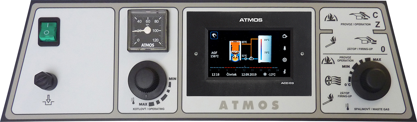
Equithermal regulation ACD 04
The boilers DC18S, DC25S, DC32S and DC40SX can be ordered from the factory with built-in ATMOS ACD 04 touch screen control.The boilers are allready equipped with all necessary sensors including flue gas temperature sensor (AGF) .This unit is designed for comfortable control of the hot water system of the heated building. The controller contains functions for direct control of the boiler, boiler circuit, three heating circuits, domestic hot water, solar, etc.
-
- Boiler control panel with equithermal regulation ATMOS ACD 04
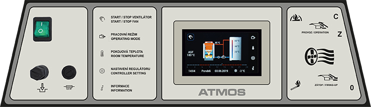
Automatic wood ignition
The automatic ignition of wood is used for planned ignition of the boiler, e.g. before coming home in the afternoon or before arriving at the cottage. The ignition of the fuel is very fast (approx. 5 minutes) and allows the operator to arrive “into the heat”. Fuel ignition can be can be set and scheduled for ATMOS AC32 regulation according to time (48h), according to the heating system requirement or according to the temperature in the accumulation tank. Automatic wood ignition is intended for DC32S and DC40SX boilers.
The ATMOS AC32 electronic regulation allows you to set the delay time or the temperature of the accumulation tank, at which the automatic ignition of wood (AIW) will occur, using the rotary wheel. If we have already installed fuel in the boiler loading chamber and poured pellets in the ignition chamber, we can proceed to planning the heating itself. Ignition can be carried out immediately, after a certain time has passed, after the accumulation tank is empty or according to a signal from a remote device (room thermostat, GSM, WiFi, etc.).
-
- Select the automatic ignition function (time/temperature) by using the switch I-O-II
Technical details
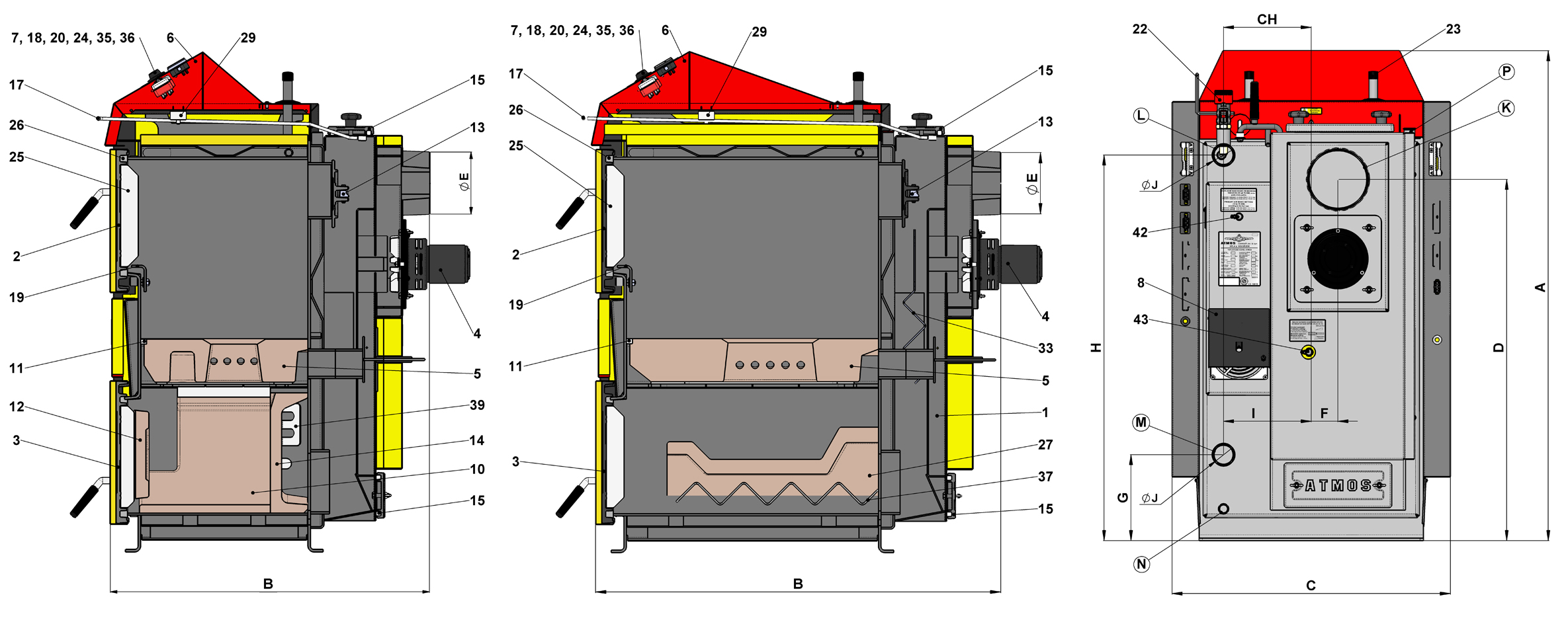
| Description of the boiler drawing | |||
| 1. | Boiler body | 23. | Cooling loop protecting against overheating |
|---|---|---|---|
| 2. | Filling door – upper | 24. | Fan control thermostat (boiler) |
| 3. | Ashtray door – lower | 25. | Door panel – Sibral |
| 4. | Exhaust fan (S) | 26. | Door seal – cord 18 x 18 |
| 5. | Heat-resistant fitting – nozzle | 27. | Heat-resistant fitting – ceramic roof |
| 6. | Control panel | 29. | Capacitor for exhaust fan – 1μF |
| 7. | Safety thermostat | 33. | Flue gas brake (DC22SX, DC30SX, DC40SX, DC50S, DC70S) |
| 8. | Control flap | 35. | Waste gas thermostat |
| 10. | Heat-resistant fitting – spherical space L + R | 36. | Safety thermostat (Caution – when overheating push on) |
| 11. | Nozzle seal | 37. | Air braker under the ceramic roof |
| 12. | Heat-resistant fitting – half-moon | 39. | Air braker along spherical space (DC18S) |
| 13. | Firing up valve | 42. | Primary air regulation |
| 14. | Heat-resistant fitting – rear part of spherical space | 43. | Secondary air regulation |
| 15. | Cleaning lid | ||
| 17. | Fire valve stem | K | – the flue-gas duct neck |
| 18. | Thermometer | L | – the boiler water outlet |
| 19. | Frame screen | M | – the boiler water inlet |
| 20. | Switch with an indicator light | N | – filling valve pipe sleeve |
| 22. | Draught regulator – HONEYWELL FR124 | P | – sleeve for a sensor of the valve which regulates the cooling loop |
| Boiler dimensions (mm) | |||||||
|---|---|---|---|---|---|---|---|
| DC18S | DC22S | DC25S | DC30SX | DC32S | DC40SX | DC50S | |
| A | 1185 | 1185 | 1185 | 1185 | 1260 | 1260 | 1260 |
| B | 758 | 959 | 959 | 959 | 959 | 959 | 1160 |
| C | 675* | 675* | 675* | 675* | 678 | 678 | 678 |
| D | 874 | 874 | 874 | 874 | 950 | 950 | 950 |
| E | 150 / 152 | ||||||
| F | 65 | 65 | 65 | 65 | 69 | 69 | 69 |
| G | 208 | 208 | 208 | 208 | 185 | 185 | 185 |
| H | 933 | 933 | 933 | 933 | 1008 | 1008 | 1008 |
| CH | 212 | 212 | 212 | 212 | 256 | 256 | 256 |
| I | 212 | 212 | 212 | 212 | 256 | 256 | 256 |
| J | 6/4″ | 6/4″ | 6/4″ | 6/4″ | 6/4″ | 6/4″ | 2″ |
| Specification | Boiler type | |||||||
| DC18S | DC22S | DC25S | DC30SX | DC32S | DC40SX | DC50S | ||
|---|---|---|---|---|---|---|---|---|
| Boiler heat output | kW | 20 | 22 | 27 | 30 | 35 | 40 | 49,9 |
| Boiler thermal input | kW | 22,2 | 24,5 | 30,0 | 33,4 | 39,4 | 45,0 | 56,9 |
| Heating surface | m2 | 1,8 | 2,1 | 2,3 | 2,3 | 2,9 | 2,9 | 3,8 |
| Fuel shaft volume | dm3 (l) | 60 | 95 | 95 | 95 | 135 | 135 | 180 |
| Filling hole dimensions | mm | 450 x 260 | 450 x 260 | 450 x 260 | 450 x 260 | 450 x 260 | 450 x 260 | 450 x 260 |
| Prescripted chimney draft | Pa / mbar | 18 / 0,18 | 23 / 023 | 23 / 0,23 | 24 / 0,24 | 24 / 0,24 | 24 / 0,24 | 25 / 0,25 |
| Max. working water overpressure | kPa / bar | 250 / 2,5 | 250 / 2,5 | 250 / 2,5 | 250 / 2,5 | 250 / 2,5 | 250 / 2,5 | 250 / 2,5 |
| Boiler weight | kg | 269 | 324 | 326 | 332 | 366 | 368 | 433 |
| Gas-outlet pipe diameter | mm | 150 / 152 | 150 / 152 | 150 / 152 | 150 / 152 | 150 / 152 | 150 / 152 | 150 / 152 |
| Ingress protection of electric parts | IP | 20 | 20 | 20 | 20 | 20 | 20 | 20 |
| Electrical power input (auxiliary) | W | 50 | 50 | 50 | 50 | 50 | 50 | 50 |
| Electrical input in standby mode | W | 0 | 0 | 0 | 0 | 0 | 0 | 0 |
| Ignition mode | manual | |||||||
| Efficiency over the entire performance range | % | 90,1 | 89,9 | 89,9 | 89,9 | 88,9 | 88,9 | 87,7 |
| Useful efficiency at nominal output (ηn) | % | 82,0 | 82,5 | 81,9 | 81,9 | 81,0 | 81,0 | 79,8 |
| Boiler class | 5 | 5 | 5 | 5 | 5 | 5 | 4 | |
| Boiler category | 1 | |||||||
| Operating mode | non-condensing | |||||||
| Solid fuel boiler with cogeneration unit |
no | |||||||
| Combined device also for heating of DHW | no | |||||||
| Energy efficiency class | A+ | A+ | A+ | A+ | A+ | A+ | A+ | |
| Waste gas temperature at nominal output according to EN303-5 | °C |
157 | 177 | 177 | 177 | 185 | 185 | 204 |
| Flue gas temperature / draft for calculating the flue gas path (chimney) | °C / Pa | 177 / 18 | 187 / 23 | 187 / 23 | 187 / 24 | 195 / 24 | 195 / 25 | 214 / 25 |
| Waste gas combustion products flow weight at nominal output | kg / s | 0,012 | 0,013 | 0,014 | 0,017 | 0,020 | 0,023 | 0,029 |
| Specified fuel (preffered) | Dry wood with a calorific value of 15 – 17 MJ/kg-1, water content 12 – 20 %, diameter 80 – 120 mm | |||||||
| Average consumption for the heating season | kg.h-1 | 20 | 22 | 25 | 30 | 35 | 40 | 50 |
| Prescribed wood length | mm | 330 | 530 | 530 | 530 | 530 | 530 | 730 |
| Combustion time at nominal output | Hours | 2 | 3 | 3 | 2 | 3 | 2 | 3 |
| The volume of water in the boiler | l | 45 | 58 | 58 | 58 | 80 | 80 | 89 |
| Boiler hydraulic loss | mbar | 0,18 | 0,21 | 0,21 | 0,21 | 0,20 | 0,20 | 0,22 |
| Minimum buffer tank volume | l | 500 | 500 | 500 | 500 | 500 | 500 | 750 |
| Connecting voltage | V / Hz | 230/50 | ||||||
| EKODESIGN | Yes | Yes | Yes | Yes | Yes | Yes | Yes | |
High performance boilers
Wood gasification boilers are suitable not only for family houses, but also for businesses premises. High performance boilers are widely used in carpentry shops, manufacturing plants, schools and mountain huts. Every place, where wood is available as cheap fuel. The boilers can be arranged next to each other in a cascade and operated according to the current heat losses of the building.
The advantage of the DC100, DC105S and DC150S boilers is the ability to quickly change the output in two steps, due to the fact that the boilers are equipped with two fans.