
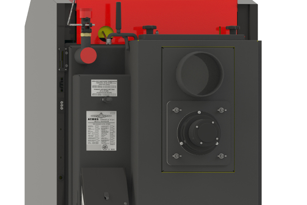
Wood gasification boiler with automatic wood ignition and ACD 04 equithermal regulation
- Automatic wood ignition
- Technical details
-
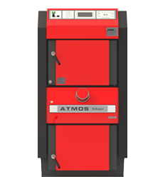
DC18GD with auto. ignition
-
Rated power 19 kW
-
Boiler efficiency 90,3 %
-
Automatic wood ignition
-
Emission class nr. 5 (Ecodesign)
-
Log lenght 330 mm


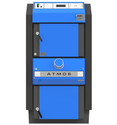
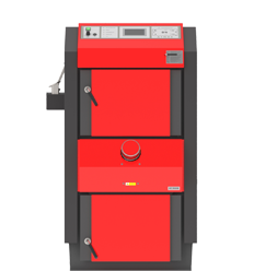
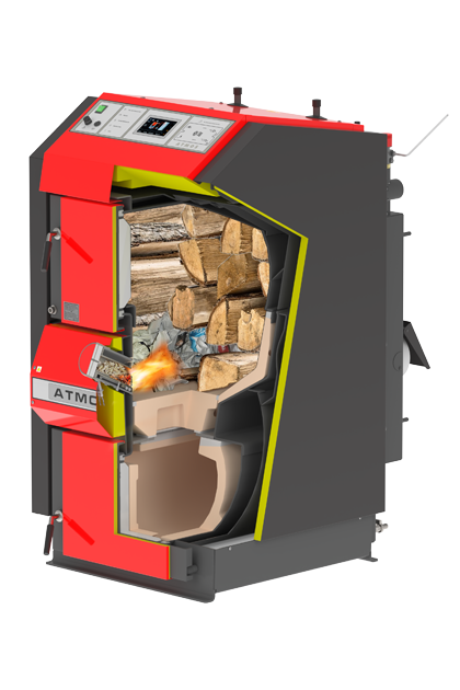
Advantages of wood gasification boilers ATMOS
- Option to burn large pieces of wood
- Large space for wood – long burning time – up to 12 hours, depending on boiler type
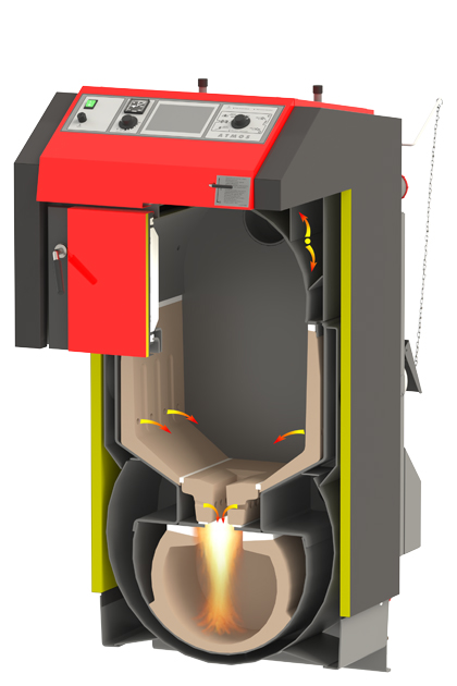
- Tube heat exchanger
- High efficiency over 90 % – primary and secondary air is preheated to a high temperature
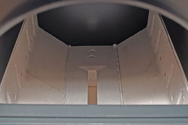
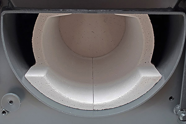
- Ceramic loading chamber – fuel pre-drying
- Ceramic combustion chamber
- Ecological burning – boiler class 5 – EN 303-5:2012, ECODESIGN 2015/1189
- Exhaust fan – dust-free ash removal, smokeless boiler room
- Cooling loop protecting against overheating – without risk of boiler damage
- Automatic shutdown of the boiler after the fuel burns out – flue gas thermostat
- Comfortable ash removing – large space for ash (when burning wood, clean it 1x / week)
- Small size and low weight
- Possibility of choosing a door R / L (right/left) for selected types
- High quality
-

- DCxxGD
-
- Combustion chamber with heat-resistant fitting – nozzle
-
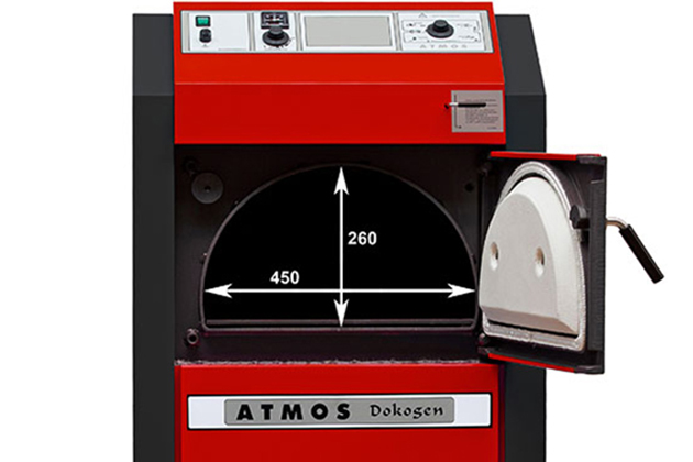
- Filling hole dimensions
-
- View of bottom combustion chamber
-
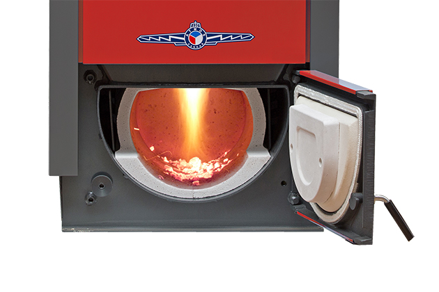
- Flame in the lower combustion chamber
-
- Draught regulator FR 124, exhaust fan and
-
- Tubesheets without air brakers
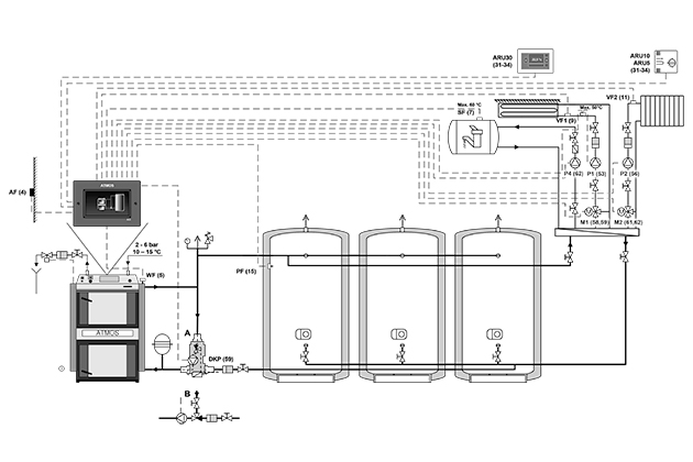
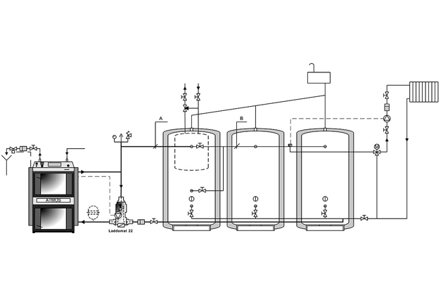
Installation
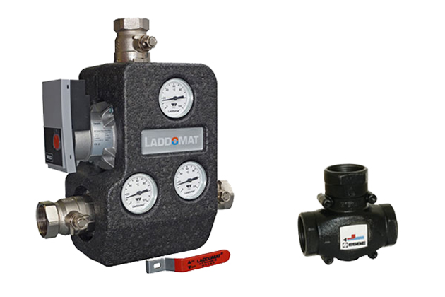
ATMOS boilers must be connected via the LADDOMAT 22 or thermoregulatory valve (three-way valve controlled with actuator) to achieve keeping the minimum temperature of water returning to boiler at 65 °C. We keep the outlet temperature of the boiler in the range of 80 – 90 °C and set the temperature of the water to the radiators or floor heating on the mixing three-way valve as needed (e.g. 30 – 80 °C).
The default configuration of all boilers includes a cooling circuit to prevent overheating. We recommend installing a boiler with accumulation tanks, which will reduce fuel consumption and increase heating comfort.
MODELS DCxxGD BOILERS ARE ONLY INTENDET FOR CONNECTION WITH ACCUMULATION TANKS OF SUFFICIENT CAPACITY WITH A MINIMUM OF 55 LITRES PER 1 kW OF INSTALLED BOILER OUTPUT.
-
- Laddomat 22
-
- Draught regulator FR 124
-
- Boiler wiring diagram with ACD 03 control and storage tanks
-
- Boiler wiring diagram with Laddomat 22 and accumulation tanks
Boilers regulation
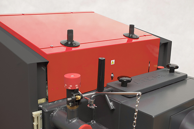
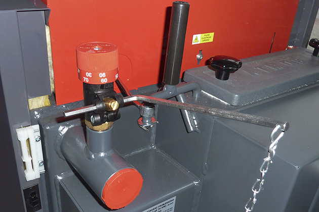
Electromechanical regulation – boiler performance is regulated by an air regulating valve controlled by a draft regulator, FR 124 type, which automatically opens or closes the air valve according to the set water outlet temperature (80 – 90 °C). In addition to performance regulation, the draft regulator helps protect the boiler against overheating. Its advantage is a quick ignition and firing up to the required output when the air valve is fully open. The boilers are equipped with a control thermostat on the instrument panel, which controls the exhaust fan according to the set water outlet temperature (80 – 85 °C) and a flue gas thermostat, which is used to shut down the boiler and turn off the exhaust fan after the fuel has burned out. In the case of connecting a boiler with accumulation tanks, the flue gas thermostat also controls the operation of the pump in the boiler circuit.
The advantage of regulation and design of ATMOS boilers is that the boilers work with a good chimney draft up to 70 % of the nominal power even without a fan.
-
- Regulating air flap
-
- Draught regulator FR 124
-
- Boiler control panel with standard regulation
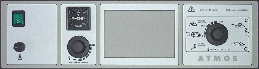
Panel composition:
Main switch, safety thermostat, thermometer, control thermostat and flue gas thermostat.
Electromechanical control is the optimal solution for controlling the operation of the boiler (fan) in a simple way. The design of the panel with standard regulation is the basic design for all manufactured boilers.
Equithermal regulation ACD 03
Each boiler can be equipped with a modern touch electronic control ATMOS ACD 03 for controlling the entire heating system depending on the outdoor temperature, room temperature and time. This regulation is able to control the boiler itself with a fan with many other functions.
-
- Boiler control panel with equithermal regulation ATMOS ACD 03
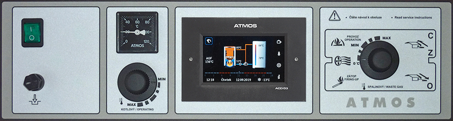
Equithermal regulation ACD 04
The boilers DC18GD, DC25GD and DC30GD can be ordered from the factory with built-in ATMOS ACD 04 touch screen control only with with combination with Automatic wood ignition (AIW).The boilers are factory-equipped with all the necessary sensors for connecting the boiler and the heating system, including the flue gas temperature sensor (AGF). This unit is designed for comfortable control of the hot water system of the heated building. The controller contains functions for direct control of the boiler, boiler circuit, three heating circuits, domestic hot water, solar, etc.
-
- Boiler control panel with equithermal regulation ATMOS ACD 04

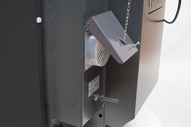
Automatic wood ignition
Automatic wood ignition is used for the planned ignition of the boiler, eg before the arrival home in the afternoon or before arrival at the cottage. Ignition of the fuel is very fast (approx. 5 minutes) and allows the boiler operator to arrive “into the heat”. Fuel ignition can be set and scheduled to control ATMOS ACD 04 according to time (weekly program), according to the requirements of the heating system or according to the temperature in the Accumulation tank.
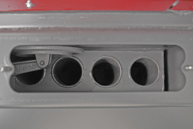
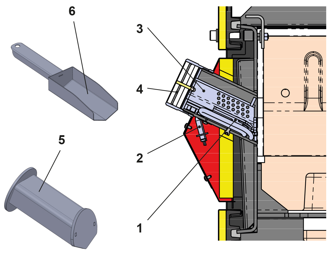
A device for automatic wood ignition is built in between the upper and lower doors (a chamber with a heating spiral). High-quality wood pellets are used for ignition, which are used to fill the ignition chamber. The amount of pellets corresponds to the size of the shovel that is included in the delivery of the boiler.
The pellets are ignited at the set moment using an electric heating spiral (500 W).
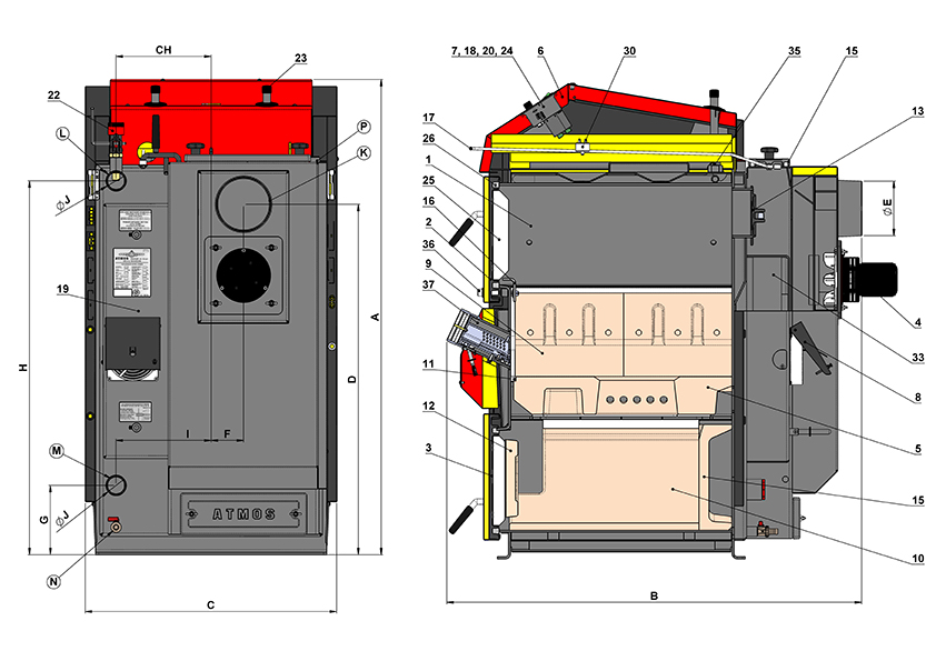
| Drawings of boilers with automatic wood ignition | Drawing of the ignition device | ||||
| 1. | Boiler body | 19. | Intake duct – air duct | 1. | Ignition spiral plate |
| 2. | Stocking door (upper) | 20. | Main switch | 2. | Ignition spiral |
| 3. | Ash-pan door (lower) | 22. | Draught regulator – Honeywell FR 124 | 3. | Removable ignition chamber |
| 4. | Exhaust fan | 23. | Cooling loop protecting against overheating | 4. | Screw lid (always tightened during operation) |
| 5. | Heatproof shaped piece – nozzle | 24. | ATMOS ACD 04 controller | 5. | Removable blanking chamber |
| 6. | Control panel | 25. | Door filling – Sibral small – thick for upper door small – thin for lower door |
6. | Pellet filling scoop |
| 7. | Safety thermostat | 26. | Door sealing – cord 18 x 18 | ||
| 8. | Regulating flap | 30. | Capacitor for exhaust fan – 1μF | ||
| 9. | Heat proof shaped piece – for type GD – combustion area side) |
33. | Tube heat exchanger (tubular) | ||
| 10. | Heat proof shaped piece – for type GD – spherical space |
35. | Pocket for thermostats (sensors) | ||
| 11. | Sealing – nozzle – 12 x 12 (14 x 14) | 36. | Locking screw | ||
| 12. | Heatproof shaped piece – half moon | 37. | Ignition device | ||
| 13. | Ignition valve | ||||
| 14. | Heat proof shaped piece – for type GD – rear face of spherical space |
K | flue gas duct neck | ||
| 15. | Cleaning lid | L | water outlet from | ||
| 16. | Frame shield | M | boiler – water inlet to | ||
| 17. | Ignition valve pulling rod | N | boiler – filling valve | ||
| 18. | Fuse T6,3A/1500 – type H | P | pipe sleeve – sleeve for cooling loop control valve sensor (TS 131, STS 20) |
||
Technical details
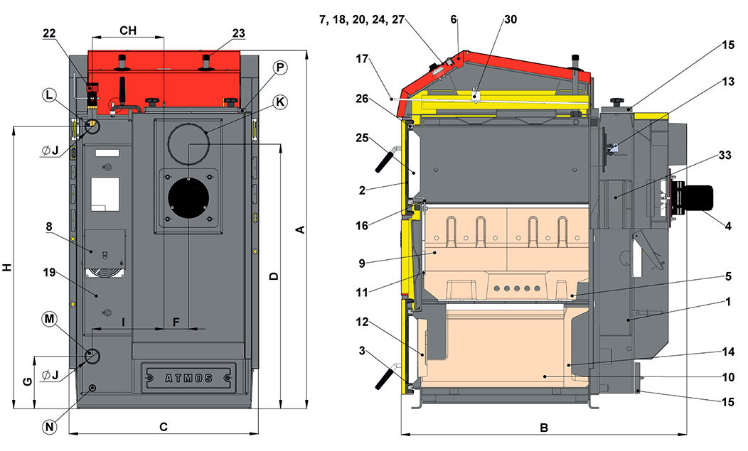
| Description of the boiler drawing | |||
| 1. | Boiler body | 18. | Thermometer |
| 2. | Filling door – upper | 19. | Supply air duct |
| 3. | Ashtray door – lower | 20. | Switch with an indicator light |
| 4. | Exhaust fan (S) | 22. | Draught regulator – HONEYWELL FR124 |
| 5. | Heat-resistant fitting – nozzle | 23. | Cooling loop protecting against overheating |
| 6. | Control panel | 24. | Fan control thermostat (boiler) |
| 7. | Safety thermostat | 25. | Door panel – Sibral |
| 8. | Control flap | 26. | Door seal – cord 18 x 18 |
| 9. | Heat-resistant fitting – side part | 27. | Waste gas thermostat |
| 10. | Heat-resistant fitting – spherical space L + R | 30. | Capacitor for exhaust fan |
| 11. | Nozzle seal – 12 x 12 (14 x 14) | 33. | Tube heat exchanger – tube sheet |
| 12. | Heat-resistant fitting – half-moon | ||
| 13. | Firing up valve | K | – the flue-gas duct neck |
| 14. | Heat-resistant fitting – rear part of spherical space | L | – the boiler water outlet |
| 15. | Cleaning lid | M | – the boiler water inlet |
| 16. | Frame screen | N | – filling valve pipe sleeve |
| 17. | Fire valve stem | P | – sleeve for a sensor of the valve which regulates the cooling loop |
| Boiler dimensions (mm) | Boiler type | ||||
|---|---|---|---|---|---|
| DC18GD | DC25GD | DC30GD | DC40GD | DC50GD | |
| A | 1281 | 1281 | 1281 | 1435 | 1435 |
| B | 820 | 1020 | 1020 | 1120 | 1120 |
| C | 680 | 680 | 680 | 680 | 680 |
| D | 945 | 945 | 945 | 1095 | 1095 |
| E | 150/152 | 150/152 | 150/152 | 150/152 | 150/152 |
| F | 87 | 87 | 87 | 82 | 78 |
| G | 185 | 185 | 185 | 185 | 185 |
| H | 1008 | 1008 | 1008 | 1152 | 1152 |
| CH | 256 | 256 | 256 | 256 | 256 |
| I | 256 | 256 | 256 | 256 | 256 |
| J | 6/4″ | 6/4″ | 6/4″ | 2″ | 2″ |
| Specifications | Boiler type |
|||||
| DC18GD | DC25GD | DC30GD | DC40GD | DC50GD | ||
| Boiler heat output | kW |
19 | 25 | 29,8 | 40 | 49 |
| Boiler thermal input | kW | 20,8 | 27 | 32,6 | 44 | 53,3 |
| Heating surface | m2 | 2,5 | 3,1 | 3,1 | 3,8 | 4,1 |
| Fuel shaft volume | dm3 (l) |
80 | 120 | 125 | 160 | 160 |
| Filling hole dimensions | mm | 450 x 260 | 450 x 260 | 450 x 260 | 450 x 260 | 450 x 260 |
| Prescripted chimney draft | Pa/mbar |
16/0,16 | 18/0,18 | 20/0,20 | 22/0,22 | 24/0,24 |
| Max. working water overpressure | kPa/bar | 250/2,5 | 250/2,5 | 250/2,5 | 250/2,5 | 250/2,5 |
| Boiler weight | kg |
376 | 469 | 466 | 548 | 565 |
| Gas-outlet pipe diameter | mm | 150/152 | 150/152 | 150/152 | 150/152 | 150/152 |
| Ingress protection of electric parts | IP | 20 | 20 | 20 | 20 | 20 |
| Electrical power input (auxiliary) | W | 50 | 50 | 50 | 50 | 50 |
| Electrical input in standby mode | W | 0 | 0 | 0 | 0 | 0 |
| Ignition mode | manual / automatic | manual | ||||
| Efficiency over the entire performance range | % |
91,5 | 92,5 | 91,3 | 90,5 | 92,0 |
| Boiler class | 5 | 5 | 5 | 5 | 5 | |
| Boiler category | 1 | |||||
| Operating mode | non-condensing | |||||
| Solid fuel boiler with cogeneration unit | no | |||||
| Combined device also for heating of DHW | no | |||||
| Energy efficiency class | A+ | A+ | A+ | A+ | A+ | |
| Waste gas temperature at nominal output according to EN303-5 | °C | 137,5 | 127 | 148 | 134,6 | 183 |
| Flue gas temperature / draft for calculating the flue gas path (chimney) | °C / Pa | 158 / 16 | 147 / 18 | 168 / 20 | 155 / 22 | 193 / 24 |
| Waste gas combustion products flow weight at nominal output | kg / s | 0,011 | 0,014 | 0,017 | 0,023 | 0,028 |
| Specified fuel (preffered) | Dry wood with a calorific value of 15 – 17 MJ/kg-1, water content 12 – 20 %, diameter 80 – 120 mm | |||||
| Average fuel consumption for the heating season | kg.h-1 | 5,1 | 6,1 | 7,7 | 10 | 13 |
| Prescribed wood length | mm |
330 | 530 | 530 | 530 | 530 |
| Combustion time at nominal output | Hours | 2 | 2 | 2 | 2 | 2 |
| The volume of water in the boiler | l |
73 | 105 | 105 | 112 | 128 |
| Boiler hydraulic loss | mbar | 0,22 | 0,22 | 0,22 | 0,23 | 0,24 |
| Minimum volume of accumulation tank | l | 1045 | 1375 | 1639 | 2200 | 2695 |
| Regulation temperature settings | °C | from 75 to 95 | ||||
| Connecting voltage | V / Hz | 230 / 50 | ||||
| Minimum return water temperature during operation | °C | 65 | ||||
| EKODESIGN | Yes | Yes | Yes | Yes | Yes | |
| All boilers in DOKOGEN line are only intendet for connection with an ACCUMULATION TANKS of sufficient capacity with a minimum of 55 litres per 1 kW of instaled boiler output. | ||||||